Design Alternative
The Design Alternative Editor allows you to edit the pipe, node and inlet constraints governing the design of the system. It also allows you to specify which gravity elements you want designed, and the extent to which you want them designed.
For example, you may want to design a particular pipe. However, you may also want to design the downstream invert elevation to meet a particular velocity, cover, and slope constraint.
The tabbed dialog for each particular type of element follows the same general format. The top of the dialog box contains several fields where the design constraints can be entered. The constraints entered in these fields are applied to every element in the table on the bottom of the dialog, except the elements that are specified to contain local values. This system allows you to rapidly enter the values that govern most of the elements in the table, and then manually override the constraints for those elements that are exceptions to the majority. The following attributes are available in this section:
Pipe diameters, invert elevations, node structures, and inlets can be all designed with the same set of design constraints. You also have the option to adjust these values individually for each pipe or structure.
The Default Design Constraints dialog is divided into the three following tabs:
Gravity Pipe Tab
The Gravity Pipe tab allows you to enter default constraints to be used for the design of pipes when performing a calculation run in design mode. The dialog is divided into the following sections:
Default Constraints Section
In this section, there is a Velocity tab, a Cover tab, and a Slope tab. You can specify the following default constraints to be used for the design of gravity pipes:
- Velocity Tab: The Velocity tab consists of the following controls:
- Cover Tab: The Cover tab consists of the following controls:
- Slope Tab: The Slope tab consists of the following controls:
Extended Design Section
This section lets you specify if the following design parameters are to be used. If they are to be used, you can also specify the associated default value. The Extended Design section is split into three tabs:
- Part Full Design Tab: The Part Full Design tab consists of the following controls:
- Number of Barrels Tab: The Number of Barrels tab consists of the following controls:
- Section Size Tab: The Section Size tab consists of the following controls:
Node Tab
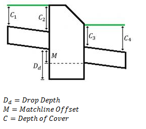
This tab lets you specify the design constraints to be used by default for all gravity structures when performing calculations in design mode. During a constraint based design, the program will adjust the elevations of the pipes adjacent to the structure according to the structure's matching constraints. The user may specify whether the connection elevation of the incoming and outgoing pipes with the structure should be matched relative to the pipes' Inverts or Crowns. Additionally, the downstream pipe can be offset from the upstream pipe(s) by a specified amount. This value is called the Matchline Offset, is measured as the relative vertical distance between either the pipes' Inverts or Crowns. Optionally, the program supports the design of drop structures. In some situations, drop structures can minimize pipe cover depths while maintaining adequate hydraulic performance. The depth of drop structure is measured vertically from the downstream invert of the incoming pipe to the sump elevation of the structure. The depth of cover is measured as the vertical distance between ground elevation and the pipe crown at each end.
Inlet Tab
This tab lets you specify the design constraints to be used for all inlets when performing a calculation run in design mode. During a constraint based design, the program will adjust the length of the inlet in order to meet the design constraints.
- For an inlet in sag, the Default In Sag Design Constraints consist of maintaining the gutter spread and water depth under a given value.
- For an inlet on a grade, the Default on Grade Design Constraints consist of ensuring that at least a given percentage of the gutter flow is intercepted.
Default In Sag Design Constraints Section
This section lets you specify the design constraints to be used for all inlets located in sag when performing calculations in design mode. During a constraint based design, the program will adjust the length of the inlet in order to meet both design constraints:
- Maximum Spread in Sag–The maximum allowed spread of water at the inlet, measured from the curb.
- Maximum Depth in Sag–The maximum depth of water allowed at the inlet.
Default On Grade Design Constraints
This section lets you specify the design constraints to be used for all inlets located on a grade when performing a calculation run in design mode. During a constraint based design, the program will adjust the length of the inlet in order to meet a minimum inlet efficiency, or percentage of gutter flow intercepted by the inlet, that you specify.
The lower section of the dialog allows you to specify local data. In order to specify that an element contain local data, place a check mark in the column labeled Specify Local Constraints on the same row as the element. When the check mark appears, the yellow columns that display the global design constraints defined in the top of the dialog will turn white on the row of the element that is being modified. This means that you can now change the design constraint values for this particular element. If you click the check mark again, the opposite happens. The columns containing the constraints turn yellow and revert to the global values entered in the top of the dialog. The following tabs are available:
Additional check boxes are available to specify exactly what you want the software to design:
For Conduits
- Design Conduit?: Check this box if you want the program to design the conduit based on the constraints you define.
- Design Start Invert?: Check this box if you want the program to design the upstream invert based on the constraints you define.
- Design Stop Invert?: Specify if the program should design the downstream invert based on the constraints given in the model.
- Specify Local Pipe Constraint?: If this box is checked, you can enter local values to replace the default values. If it is not checked, the program will automatically use the default constraints.
For Nodes
- Design Structure Elevation?: Check this box if you want to allow the structure's sump elevation to be adjusted during a constraint based design. When this box is checked, the Desired Sump Depth field becomes editable.
- Desired Sump Depth: This field becomes editable when the Design Structure Elevation? box is checked. The sump depth is the distance below the lowest pipe invert.
- Local Pipe Matching Constraints?: If this box is checked, you can enter local values to replace the default values. If it is not checked, the program will automatically use the default constraints.
For Inlets
- Design Inlet Opening?: Check this box if you want to allow the Inlet Opening to be adjusted during the constraint based design.
- Specify Local Inlet Constraints?: If this box is checked, you can enter local values to replace the default values. If it is not checked, the program will automatically use the default constraints.